 English
 Hello everyone!
In this tutorial, I want to share one of the ways to create textures for flat objects such as tiles or 3D panels.
I use this method quite often as it is faster than painting a texture from scratch in Photoshop. Plus, in a couple of clicks, you can quickly create a bump map.
I guess that it is not necessary to additionally say that using textures instead of 3D geometry saves resources significantly. Especially if you build scenes in Unreal Engine, Unity or WebGL. And the result will be no worse.
Tell in the comments your cases of using this method and how you create such textures...
Introduction

Picture taken from the site: https://www.daltile.com/product/Bee-Hive-Medley?color=White&shape=Hexagon
As we can see, the tile has a complex pattern, and hand drawing in Photoshop will take quite a long time. Therefore, in this method, we first create the tile geometry, apply textures to it, then just render it. Thus, we have a more flexible approach and can, in the process, change the direction of the texture for individual tiles, or change something without global alterations.
Read the lesson to the end and perhaps you will learn about some nuances or new tricks.
Modeling
Always, before the modeling stage, it is necessary to carefully study the reference in order to break the work into small stages and understand the design or structure of the object.

As you can see in the picture above, our tile consists of hexagons with a specific pattern that divides our honeycomb into three rhombuses.
The row below is the same tile, only turned 180°.
The tiles adjoin each other at a certain angle, about 60°.
Create a hexagon using Spline → NGon.

To do this, go to the Top view, click NGon, set the number of sides to 6 and the size to 24.77 cm.
The size is taken from the specification indicated on the official website.

Next, convert this spline to Editable Poly by clicking the right mouse button on the selected object and select Convert To → Editable Poly.

Go to the polygon editing subobjects or press the 4 key on your keyboard. Select the only polygon, make a small Insert.

Make another Insert and then click Collapse. You should end up with the image below.

Select the faces, press the 2 button to work with edges. Highlight as shown in the image below and press Backspace on your keyboard.
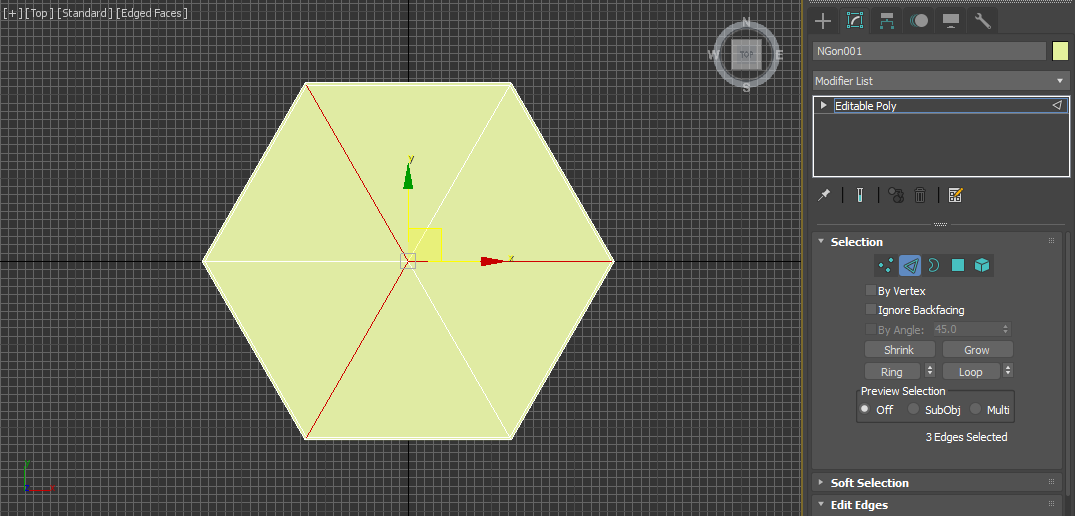
You should get it like this.

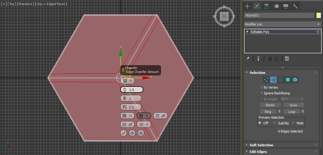
Chamfer the following faces with these settings.
You can change the scale slightly by eye to make the lines straight. Select the polygons as in the picture and apply a little Scale.

Extrude the polygons to define the height of the tile.

As a result, you should have such a tile.

Texturing
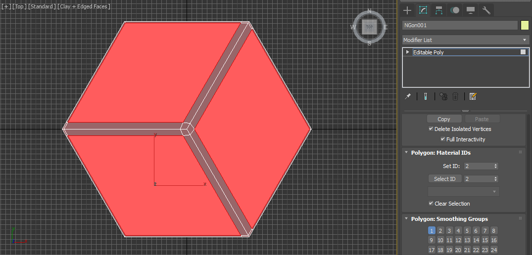
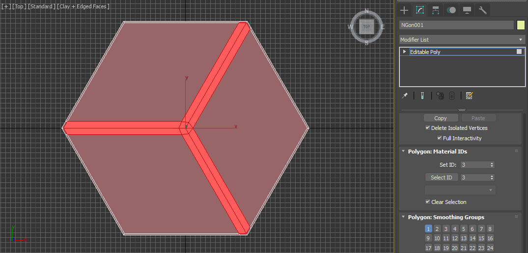
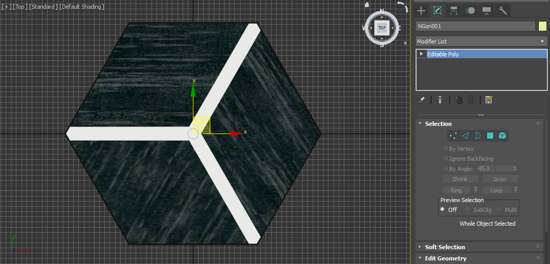
Let's split our tile into three Material IDs. See the pictures below for how to apply IDs.

Open the Material Editor (M key on your keyboard), create a Multi / Sub-Object Material with three slots and assign a Standard Material to each of the slots.

Set Diffuse Color:
For ID 1 RGB: 2 2 2
For ID 2 RGB: 38 49 50
For ID 3 RGB: 239 243 235
See the picture below for an example of color setting.

For the Diffuse Texture for ID 2, I assigned this texture below. You can either take it or create it in Photoshop using the Clone Stamp tool using a picture from this site as a basis: https://stoneandtileshoppe.com/products/bee-hive-medley-p048-cube-hex-negative-matte-porcelain-tile
Apply UVW Xform modifier to individual polygons, change Rotation and V Tile if needed.
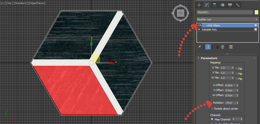
See the final result in the picture below.
Thus, we have created one tile element with three ID materials: black seams along the edges, a pattern with three white stripes and a wood texture.
Rendering
Clone the tiles using the Shift key as shown in the GIF below. Use Tools → Transform Toolbox and Vertex binding for convenience.

The cloning result should look like this. See the picture below.

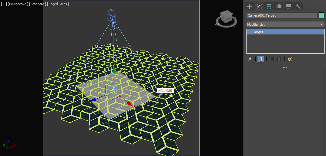
Attention! Now for an interesting trick. We will create a Plane to fit the repeating pattern. This will further help us to conveniently cut out the texture in Photoshop.
Now the most important part will be, we need to create a Plane, according to the size of the repeating pattern. Imagine Plane is a rectangular area that we will cut out later, and it should repeat seamlessly.
For convenience, I created a Plane with a minimum number of segments, converted it to Editable Poly, raised it slightly above the tile, then using the Alt+X key combination, I made our Plane semi-transparent. Further moving the vertices, I got the following result.

Place the Pivot Point for the Plane in the center, for this you can use the same Transform Toolbox by clicking the Center button in the Align Pivot group.

Build a regular Free Camera in Top view, and using the Align tool, center align our Plane.

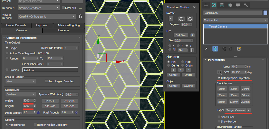
Go to the Render Setup, set the size to 5000x5000px, enable Safe Frame for the Viewport using the Shift+F keys.
For the camera, enable the Orthographic Projection option and set the Type→Target Camera. Press the C key to enable the camera view.
Move the Camera Target along the Z axis to 0 coordinates. And when raising or lowering the camera along the Z axis, adjust the angle so that Plane is fully visible in the camera.
My scene looks like the picture below.
Attention!
It is important that the Camera Target is flush with the lowest point of our tile.
Make sure you have Scanline Renderer set as the render.
Hide Plane then render F9, our texture.

Save the render in PNG format by clicking on the Floppy icon.
Now we need to hide the tile and render our Plane. Then save also in PNG format.

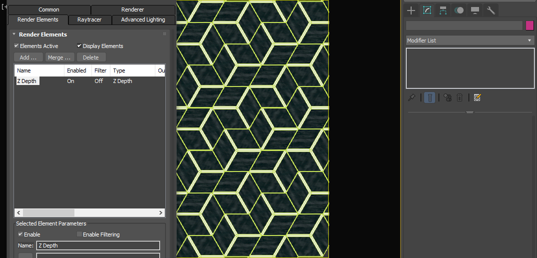
To create a bump map, you need to add a new Render Element→Z Depth in the Render Setup settings.
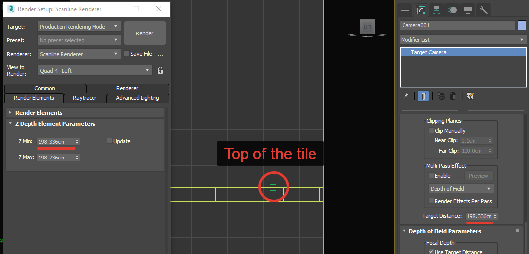
Make the following settings for Z Depth. Select the camera, copy the Target Distance to the Z Max parameter.

Next, I selected the Camera Target, moved it with the Z axis anchor to the top of the tile, and copied the Target Distance to Z Min. Then, returned the Camera Target to 0 Z coordinates.
Important!
Don't forget to move the Camera Target to its original position - 0 coordinates on the Z axis! Otherwise, you will have the wrong pattern!
Hide the Plane, turn on the camera view and start the render F9. If you did everything correctly, you should start rendering our bump in a separate VFB.

Save this render as PNG too.
At this point, all rendering is complete. We got high quality tile textures and bump maps. Thanks to Scanline Renderer, we got images without color distortion and in high resolution, which is what we needed.
It remains only to cut the desired pattern in Photoshop.
Working in Photoshop
Open Photoshop, load the resulting 3 textures onto the stack. To do this, go to File→Scripts→Load Files into Stack.

Press Ctrl+Left Mouse Click to select the opaque area. Thus, we get a quick selection of the repeating area we need. Thanks to the Plane that we created as a helper object, all we have to do is Crop this area.

To Crop without removing the selection, turn on the Crop tool or press the C key and then press Enter.
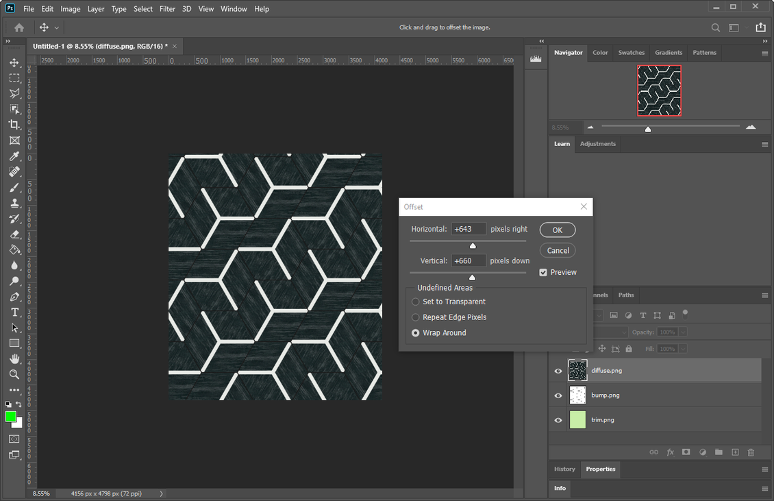
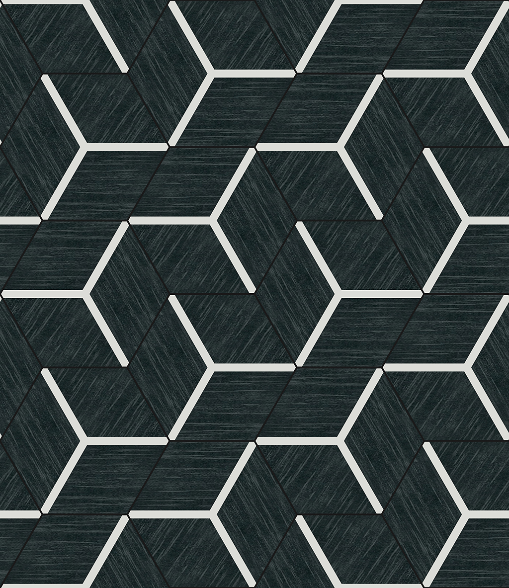
Try to then apply Filter→Other→Offset to make sure the texture has no seams.
Well done! The texture looks great!
Now you can save the final textures. To save the bump map, hide the layer above and save it with a different name. The layer with the render Plane, we no longer need.
Bonus content
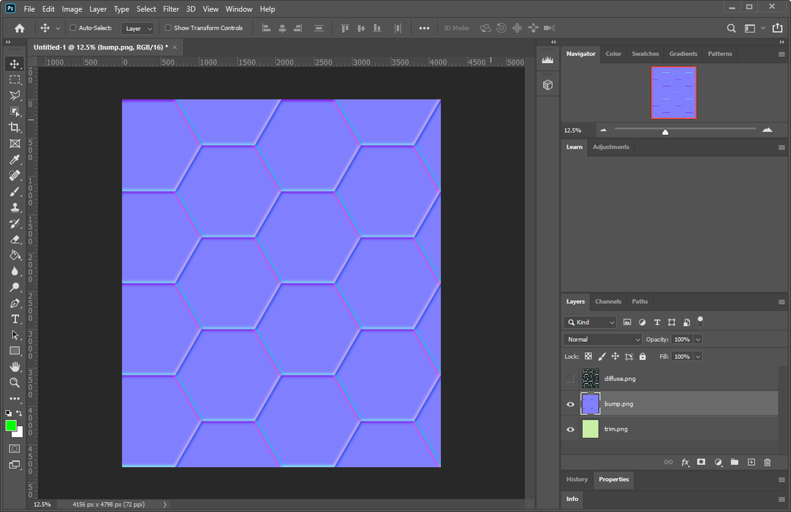
If you need to get a Normal map instead of a black and white height map, this can be easily done in Photoshop.
Go to Filter→3D→Generate Normal Map...
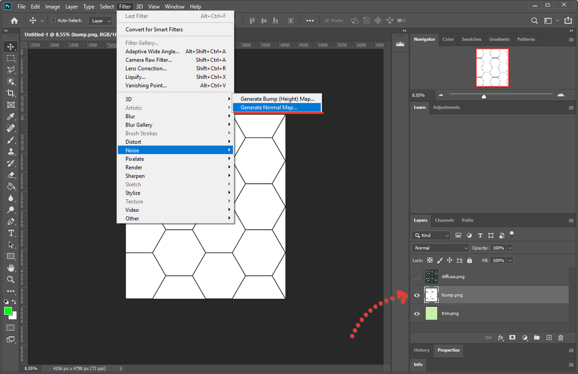
Adjust the extrusion and blur.

Done!
If you still have questions, you can watch the video attached at the beginning of the lesson. Or ask in the comments.
Also tell us how you create such textures and if this method was useful to you 😉
Final result
This is how Diffuse+Normal looks like in PlayCanvas WebGL, it looks nice.

Attached are the two textures that I ended up with.


{{comment.text}}